Titan Tank IR Protocol
The schematics are included. The controller has an EM78P156 microcontroller on it, implying custom code. The main chip on the robot is an EM78P156ELPJ-G microcontroller. One of the robots had the ID removed but the second had a very poor dot of paint on top of the part number that we just rubbed off.
Remote Control Data Stream
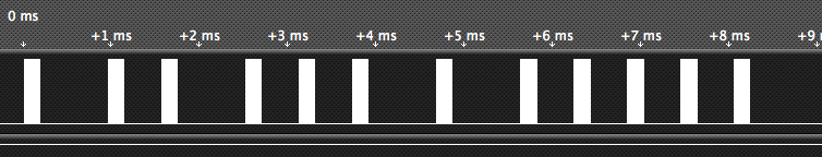
SPECIAL NOTE: We have two remotes and two robots. One of the remotes can control either robot, but the other remote can only control one robot. The logic analyzer outputs are from the second remote and it appears to have a slightly too-fast frequency on the IR transmitter, so it’s hit-or-miss as to whether any given robot works with it. Turns out that one modulates at 40 KHz and the other is way-off at 43 KHz. I tack-soldered two wires to the IR transmitter LED on one of the remotes and connected it to a logic analyzer to decode the data stream. Each bit starts with a burst of IR energy modulated at about 40 KHz, but one of my remotes modulates at 43 KHz:
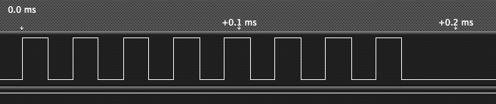
Each burst is about .1755 ms, which is then followed by either a long or short gap.
- Wide gap width: .7787 ms
- Narrow gap width: .43 ms
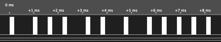
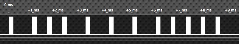
Some snapshots of data. All four of these were the FIRE button being pressed. The first is while the remote was on channel A, the second on B, etc. Keep in mind the “solid” white areas are about 40 KHz modulation:
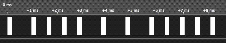
Pulse width modulation, kind of like the RECS 80 code but not quite. Since Elenco used its own processor for this, they probably just took a good idea but didn’t worry about meeting any standards for IR remotes and such. It looks like each command has 12 bits. Since it’s kind of like RECS 80, I’ll declare (it’s good to be king) that a high followed by a short gap is a 0 bit while a high followed by a long gap is a 1. The king has spoken. At least until someone gives me better information so I can correct my assumptions. So let’s decode those four FIRE commands for the four different channels:
- Channel A: 100011100001
- Channel B: 100101100001
- Channel C: 100111100001
- Channel D: 101001100001
So it appears three bits select the address (x = don’t care):
- Channel A: xx001xxxxxxx
- Channel B: xx010xxxxxxx
- Channel C: xx011xxxxxxx
- Channel D: xx100xxxxxxx
I won’t present all the logic analyzer outputs for each of the other commands, but here are the bits sequences for the other four buttons on the remote:
- left-top: 100010000011
- left-bottom: 100010000101
- right-top: 100010001001
- right-bottom: 100010010001
This is much simpler. There are five bits that indicate which button is pressed:
- 10AAA1BBBBB1
Where AAA are the address bits and the BBBBB bits are the buttons. The first two bits are always 10, there is a 1 between the address and button bits, and finally closing with another 1. Note that multiple button bits can be on at the same time. When a button is released, at least one message is sent with no buttons pressed, ie, the BBBBB bits are all zero. It seems more than one of these can be sent.
Robot Data Stream
Again, I tacked on two wires to the jack where the cannon’s IR LED connects and then watched the output on my logic analyzer. It’s the same basic command structure as the remote uses, although I didn’t measure modulated frequency of the bits. This is what is sent when the FIRE button on the remote is pressed and the robot “shoots” the cannon: 101100011001 Address: 110 (different than any combination sent by the remotes) Button bits: 01100 (can’t be duplicated by the remotes) I only checked one robot so far and found the protocol is exactly the same as that used by the remote, except that the address is 110 (the controller’s address does not matter) and the button bits are 01100, which indicates both of the buttons on the left side control are pressed, which you can’t normally do because the clear orange rocker switch lets you press only one at a time.