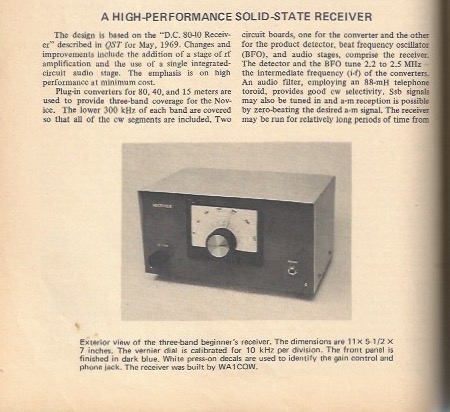
High Performance Receiver
When first getting involved in ham radio, my mother allowed me to buy a 1973 ARRL Handbook, which contained a wonderful receiver project on page 284. At age 10 I certainly didn’t have the knowledge or experience to build it, but it was always on my to-do list. Around 2018 I decided to finally get started and began to accumulate parts, then did a lot more studying of the design and purchased more parts while in the hospital in June 2019. Once out of the hospital, I began breadboarding the design.
The receiver was original published in the October 1972 issue of QST, so ARRL members can find the original article in the on-line archives. I was looking at eBay one day and found someone selling a couple issues of QST from era including this one so I bid and won the collection.
The base receiver covers 2-2.25 MHz, which is not a ham band, so plug-in converter modules are needed. Since this is designed for Novices of that era, the parts list for 80, 40 and 15 meter converters are provided. We (Novices) didn’t have any 20 meter allocation back then. The receiver is meant for CW reception, as that was the only mode we were allowed and we were all working to improve our code speed in preparation for the General 13 WPM CW test.
Sourcing Parts
Many of the vendors are no longer in business 47 years after the original article was published, so it took some digging to find either the right parts or acceptable substitutes.
T1 calls for a part no longer made, but I found Triad Magnetics SP-20 or SP-22. I opted for the SP-20. Available at Digikey, Mouser, etc.
The chassis and boxes for band converters are still made by Bud and available new from Digikey and Mouser!
Quite a few of the parts came from my junk box (ham-speak for stuff I already had) but places like Dan’s Small Parts and Surplus Sales of Nebraska have 90% or more of the components needed. I found Alltronics (not All Electronics) to have a very substantial assortment of silver mica capacitors, but only on their eBay store, not their main web page.
The beautiful dial used on the original is pure unobtainium. Several old vernier dials have appeared on eBay but most of them looked a bit too old for my project, so I ended up making my own.
Deviations from Original Circuit
Very few. I toyed with using 78xx regulators instead of the zener diodes, but stuck with the diodes.
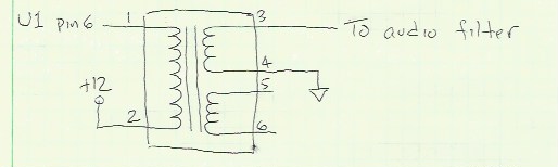
T1 Replacement
One minor change is that the T1 audio transformer is no longer available, or at least I couldn’t find it, so I replaced it with a Triad Magnetics SP-22 which is readily available from Digikey and other sources.
Audio Amplifier
The only major change is that instead of the 741 opamp based audio amp, I went with an LM386. The old design was for high-Z headphones but everything I use is 8 ohms. There are many designs of audio amplifiers based on the LM386 but I opted to simply re-use a design from another DeMaw based receiver.
Do not install these components for the IF board:
- U2 – 741 op amp
- R7 – 820K
- R8 – 10K
- R9 – 5600 ohm
- R10 – 10K
- C12 – 10uf/15v
- C19 – 150uf/15v
Instead, use this circuit which I took from another W1CER/W1FB receiver. The IC wasn’t labeled when I scanned this, but it’s a plain ol’ LM386 audio amp:
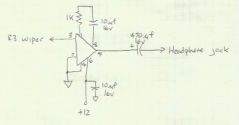
Most headphones in this day and age use a 1/8″ plug, but I opted to stay with an old-time 1/4″ jack. Headphones are now all stereo so I went with a stereo jack and simply connected both channels together. Using a common 1/4-to-1/8″ adapter allows any of the headphones in my shack to work nicely.
Band Converter Modules
The receiver covers 2.2 to 2.5 MHz so plug-in converters are used to cover bands of interest. The design uses the same basic circuit for 80, 40 and 15 meters (Novice bands of the time) but with different values for the inductors and capacitors, and a slight change to the audio amplifier for 15 meters. The same PC board design works for all three converters.
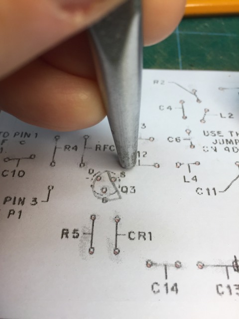
My normal approach to making PC boards involves laying them in a CAD package, then sending the GERBER files to a PC board shop to make the boards, but in keeping with the original article, I laid out the boards and etched them by hand. I haven’t hand-etched a board in 20+ years!
After checking hole alignment to be sure my components had the same spacing as the original design, I taped the PC board layout (from the original article) to the PC board. Then I used a punch to make indentations where each of the holes will eventually be drilled:
After punching:
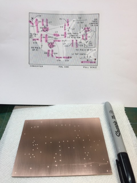
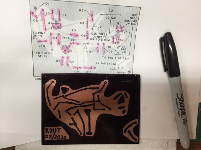
A marker was used to add etch resist:
Etching was done the old fashioned way, the board was cleaned with steel wool and hand soap, then tinned:
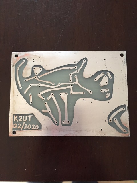
I’ve always liked tinning the boards. Even though it still looses this nice shiny finish, it looks far better than bare copper does after a few months. Yes, I could spray with conformal coating, but I just like this look better.
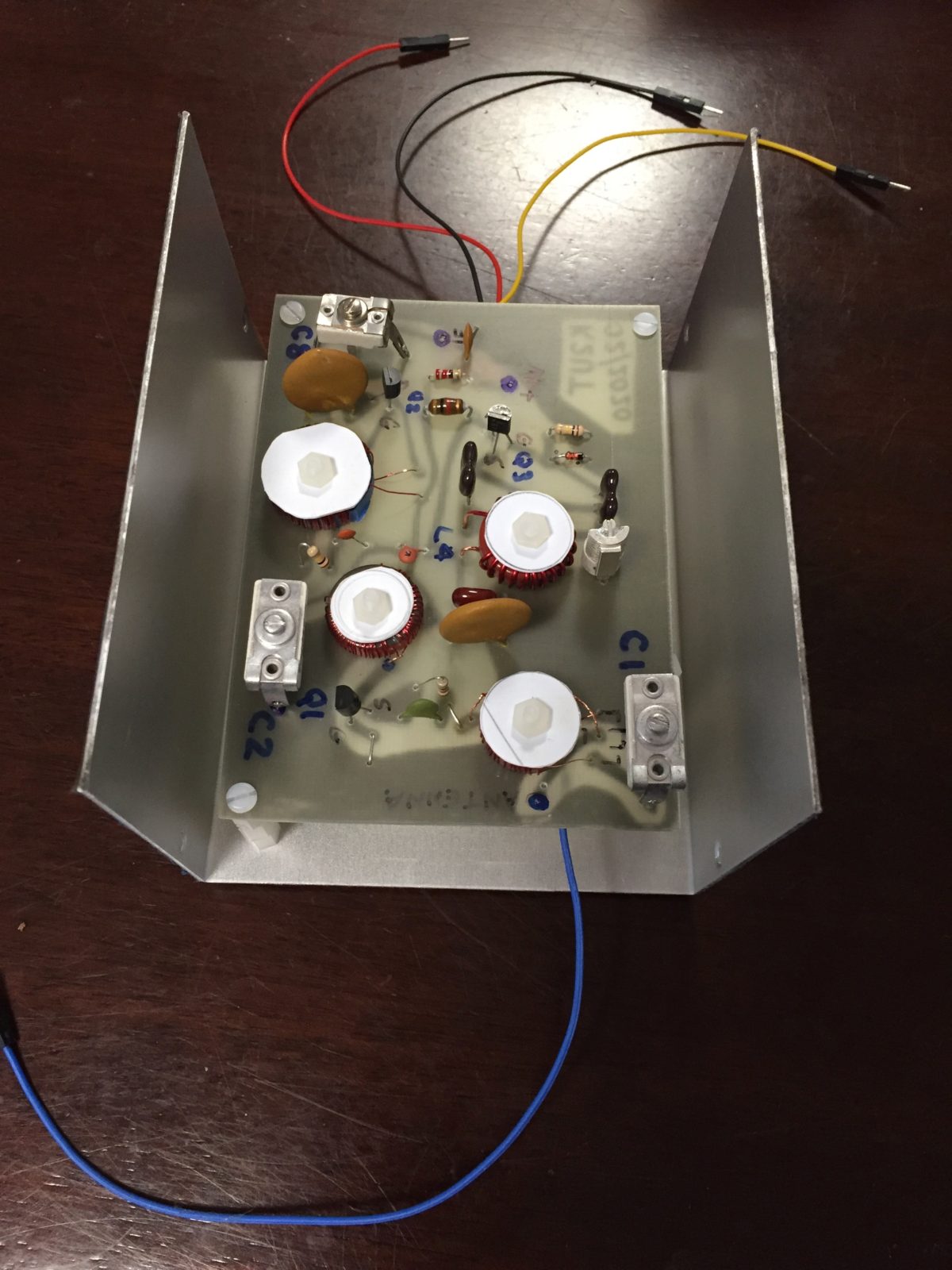
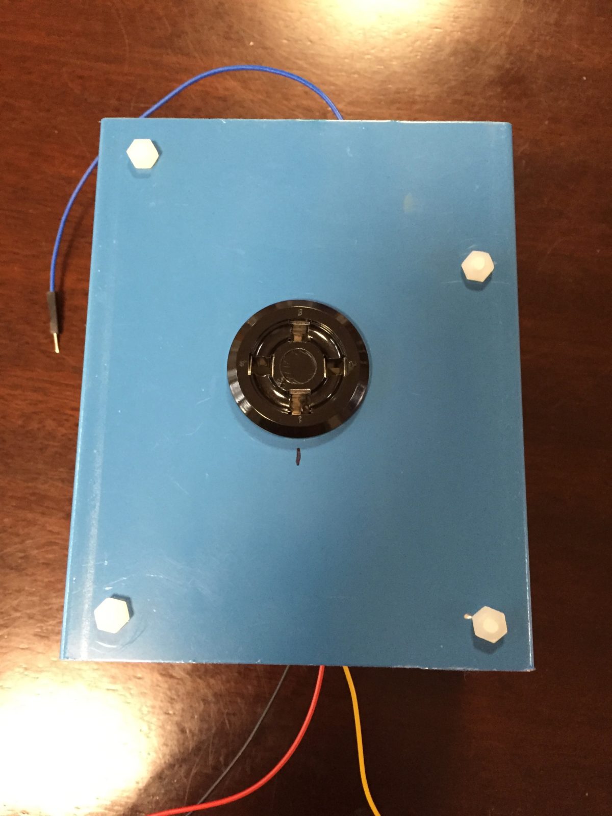
The wire with connectors are part of the initial testing. The wires plugged into the solderless breadboard where the IF and audio sections were tested. The picture above shows the converter mounted in the exact same enclosure as the original article called for. Since this picture was taken the test wires have been removed and mini coax has been used to connect the board to the socket.
The design used a four pin tube socket for the converters to plug in. People have already asked when the female connector is on the converter and not the receiver: because this allows the unused converters to sit flat on a table or shelf. Having the male connector on the converter meant they would sit oddly!
In theory, my converter should be able to plug into the original receiver and work properly.
Home Made Vernier Dial
The dial used on the original receiver is no longer made, so I kept looking on eBay and antique radio sites, but never did find one. Resigned to building one from scratch, I started by looking for the vernier mechanism itself and figured I’d be able to come up with a nice dial to go with it. Again while cruising eBay I saw someone had parted-out a Yaesu FT-101 and had the dial assembly for sale. Perfect for several reasons: (1) the FT-101 was about the same era as this receiver, and (2) an FT-101EE was my second radio.
<<more to come>>