Titan Tank Improvements
During the Boy Scout “Robo Camporee” we realized some teams just did much better than others. We had the guys swap robots to see if it was a matter of skill, luck or something else and it was soon apparent that some of the robots would not detect being shot by other robots. There was nothing I could do while several dozen tanks during the competition but the Scouts understood it wasn’t a skill issue and they just had fun in the various competitions.
Once the weekend was over, I decoded the IR protocol and began to compare “good” tanks from “bad” ones. As it turned out, both the remotes and the tanks were horribly out of timing, so sometimes a given tank might not decode commands from the remote and other times it would fire at another tank that wasn’t able to decode the “shot.”
Both the remote and tank circuits use a EM78P156 microcontroller which is configured for a resistor/capacitor timing circuit. The receiver is a 40 KHz module which is fairly tolerant to some errors, but the transmitted IR signal is modulated entire in software, so if the processor clock is off, things might not work. Since the processor uses low cost caps and resistors the timing is okay but certainly not precise. While I could carefully match high-precision resistors for each and every tank/controller, my solution was much easier: replace one of the resistors with a precision variable resistor.
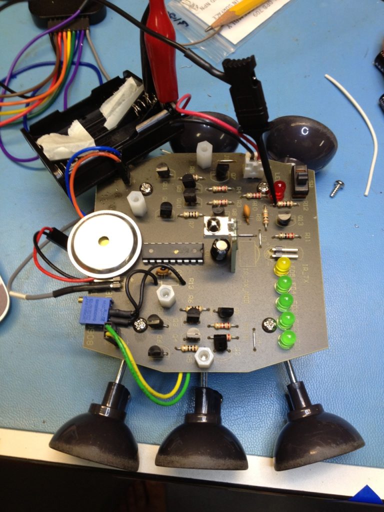
For the robot, remove R13 (3.6k) and replace with a 5k precision multi-turn trim pot. You can see I used double-sided foam tape to secure the pot to the edge of the circuit board. You can see my test points for connecting to the logic analyzer to capture/analyze the timing (R12 on the side connecting to Q13 and the ground on the BUZZER connector):

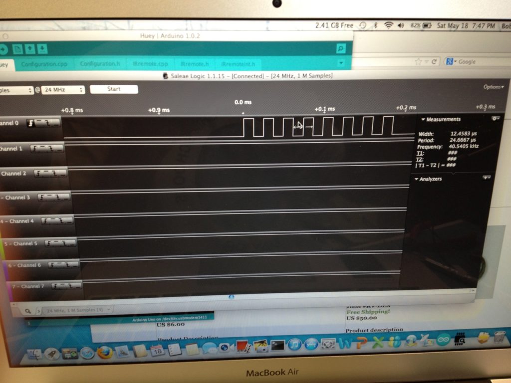
Send “fire” commands to the tank and measure the frequency of the IR modulation.
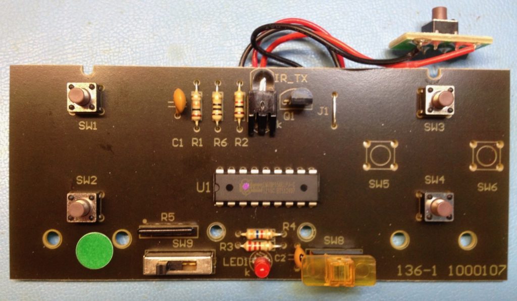
On the control box, do the same thing for R4. Here is a “before” shot:

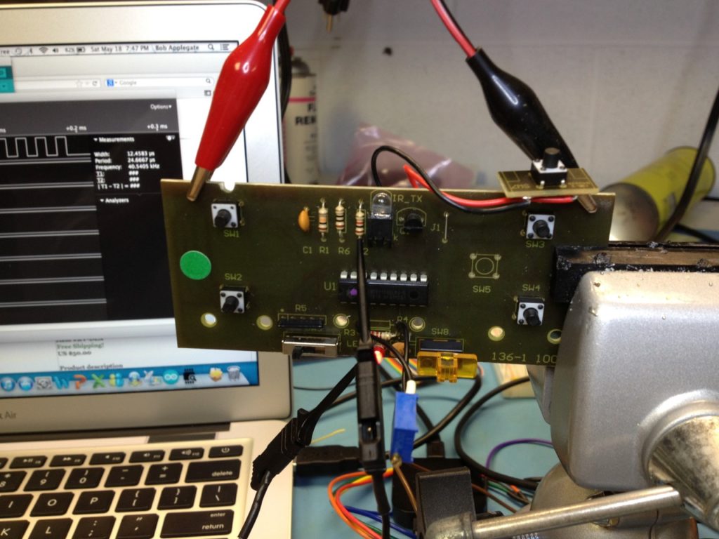
…and a somewhat messy shot showing the controller in a test jig. For test points, use R2 and a ground:

The goal is to adjust the carrier frequency to be right around 40 KHz. The closer, the better, but it does not have to be exact. This particular control box is at 40.5 KHz which is a tad high, but much better than the 47 KHz that some were set to!

So once you’ve made the mods and adjusted the variable resistor to be right on frequency, everything should work much more reliably!